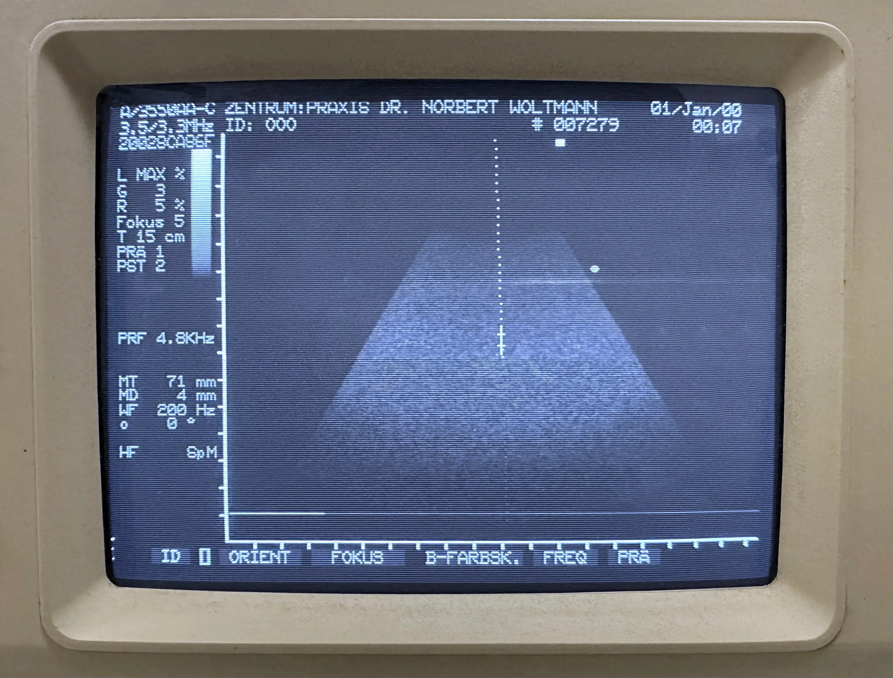
ESAOTE BIOMEDICA
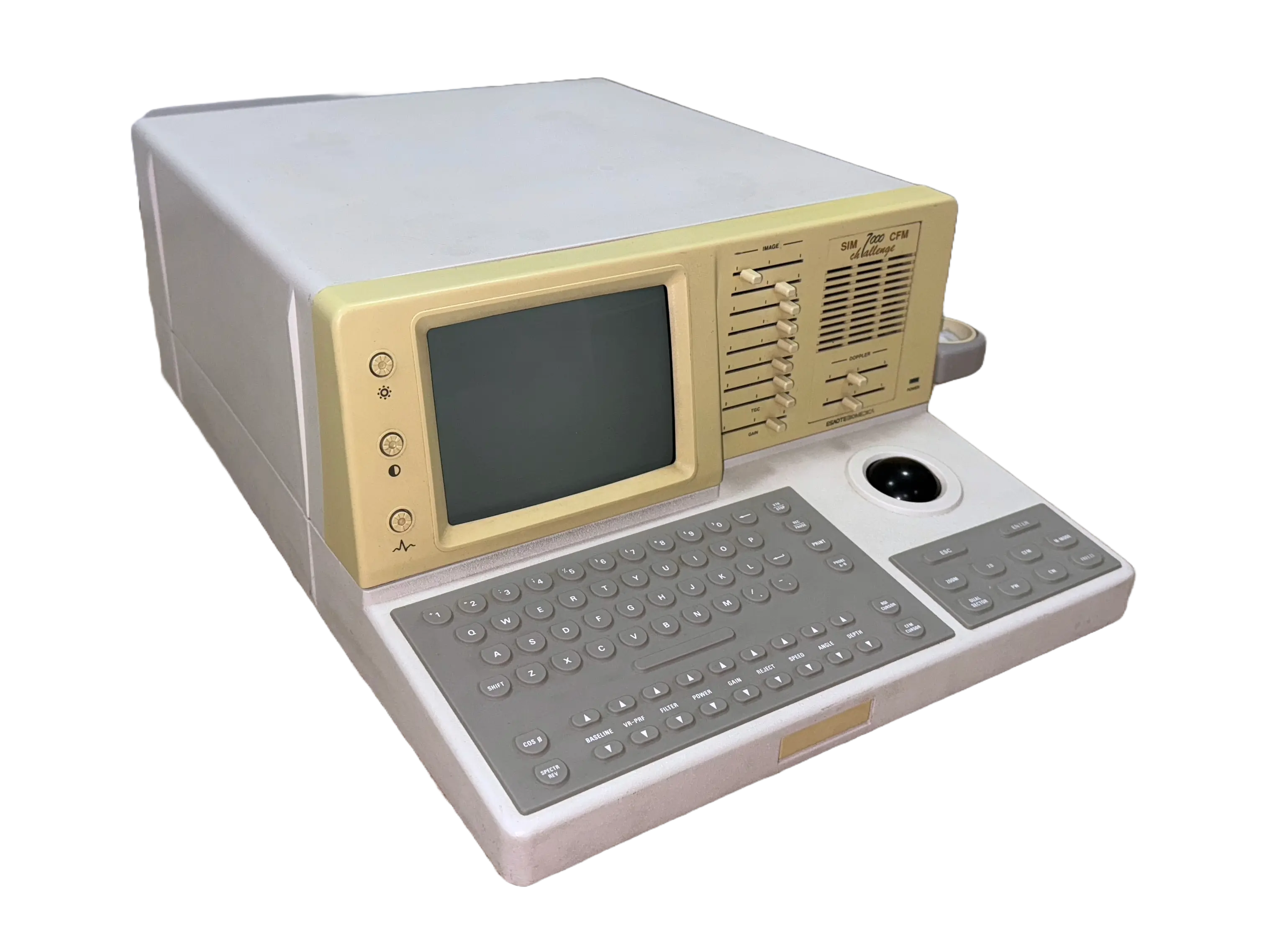
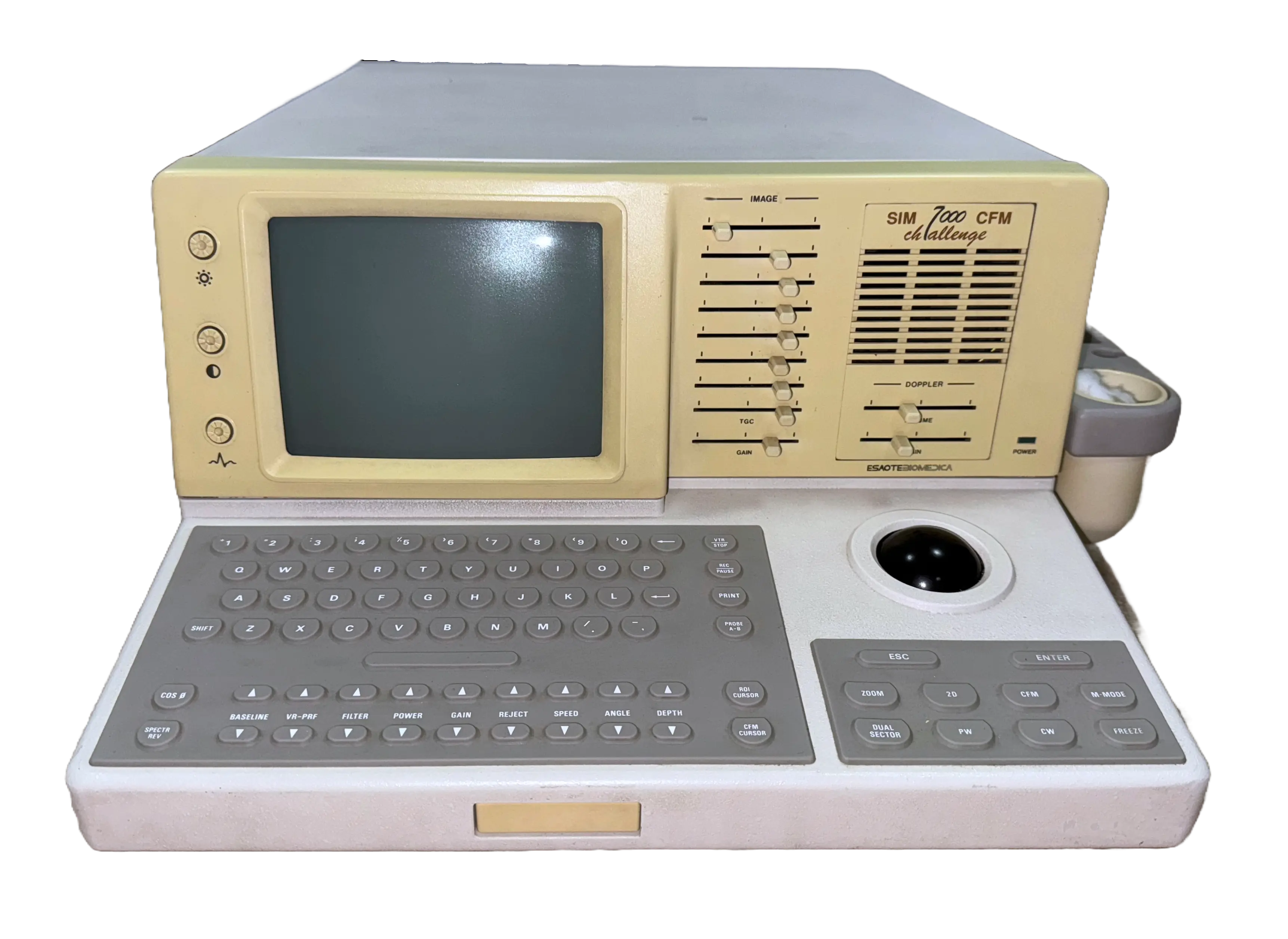
SIM CFM 7000 Challenge
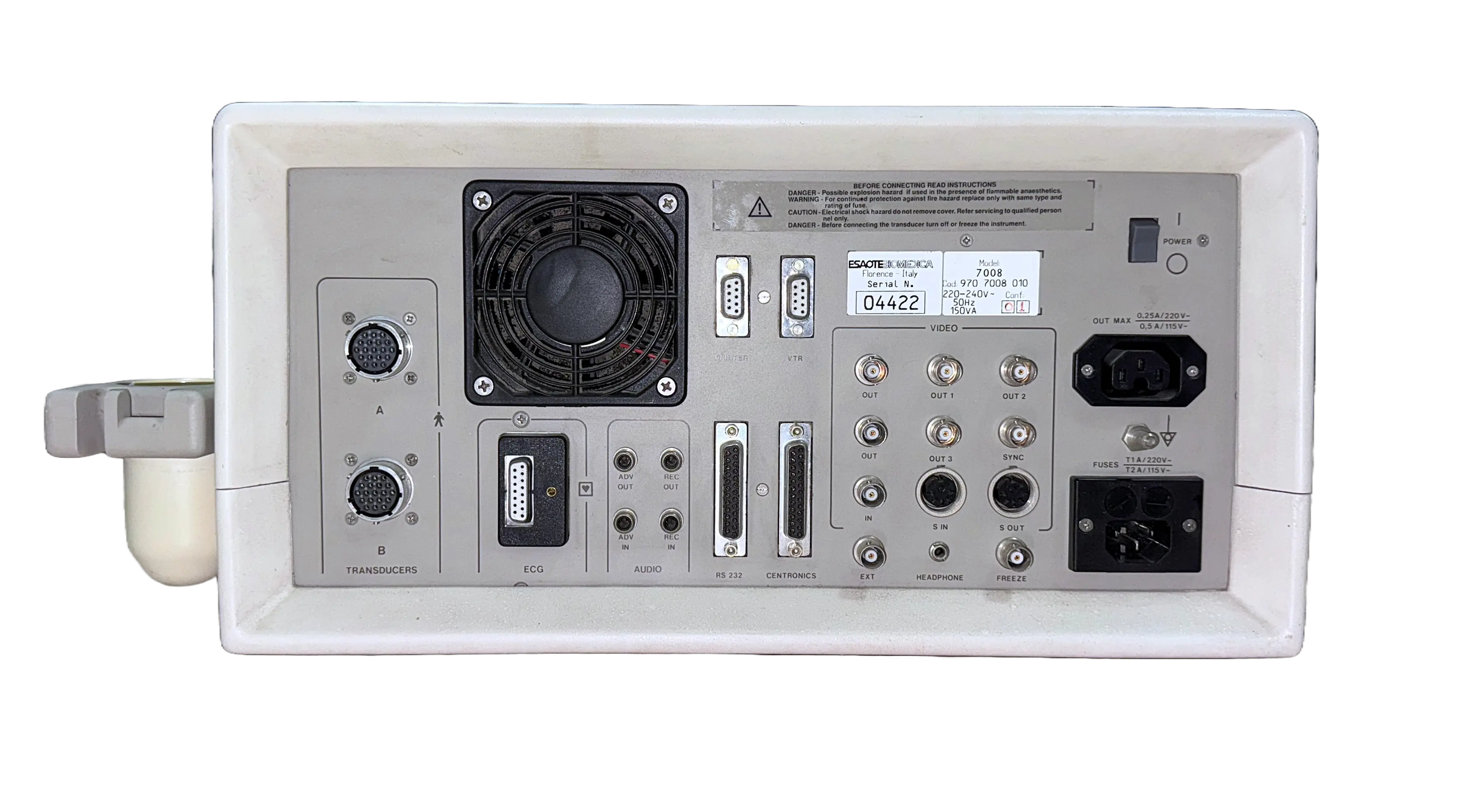
- Manufacturer ESAOTE BIOMEDICA S.p.A. / Biosound U.S.A.
- Introduced 1990 [1]
- Production Date 10/1994 (Est.)[2]
- Model/Serial 970 7008 010 SN: 04422
- Technology CW & PW Doppler, Color Flow Mapping
- Probe Types Mechanical Sector-Scanner Phased Annular Array (AA)
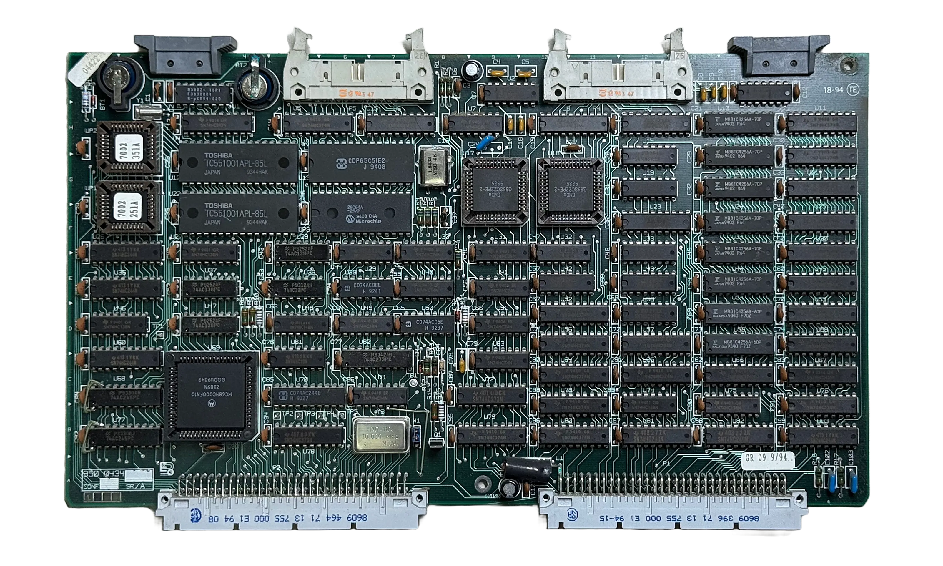
- Architecture Motorola 68K-Type CPU @ 10 MHz
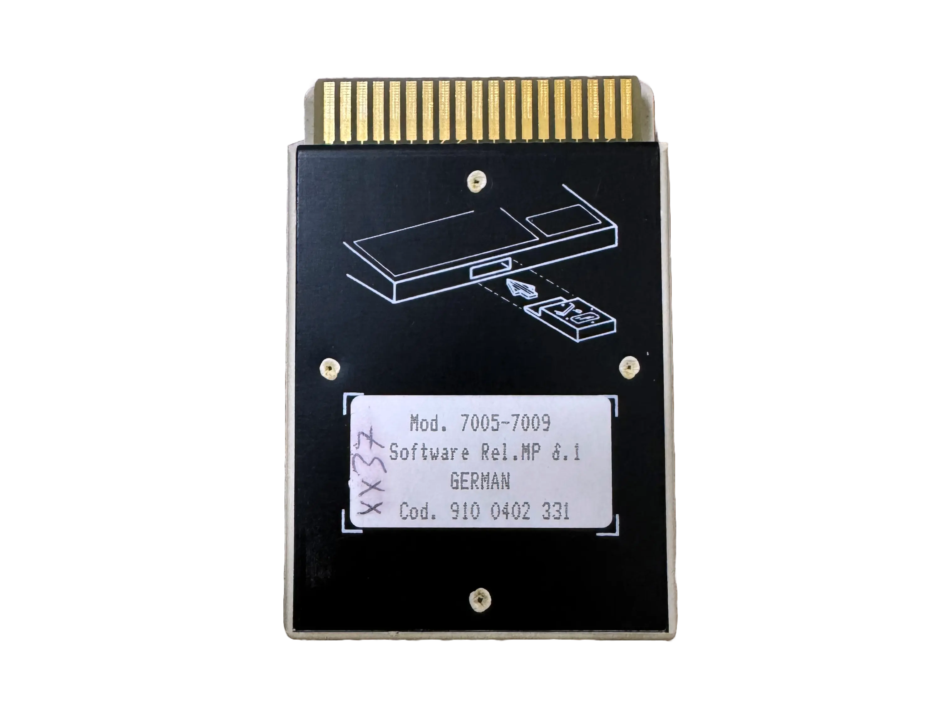
- Software Custom Real Time OS + APP PROM Cartrige
The SIM CFM 7000 represents a transitional generation of ultrasound machines, combining custom ASIC beamformers with embedded control CPUs before the widespread adoption of PC-based architectures. It was one of the first machines to feature 2D Color Flow Mapping (CFM). The SIM CFM 7000 was used by early adopters and supported annular array probes.
Because of the small probe size and its inherent functionality, requiring only a narrow beam entry, many devices were repurposed after their initial lifecycle for mobile veterinary applications. This makes complete units very rare, and fully functioning annular array (AA) probes even rarer.